
April 2010 Vol. 65 No. 4
Features
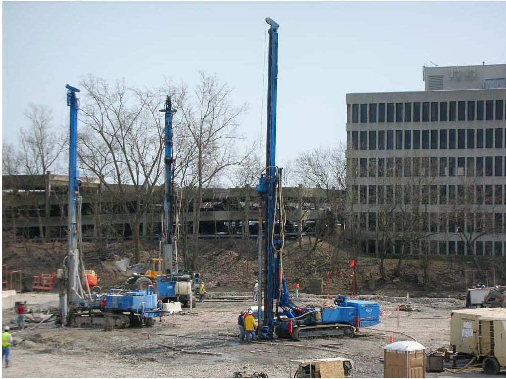
City Of Dearborn Tackles Complicated Grout ‘Curtain’ Project
Many United States municipalities and utility districts face federal Environmental Protection Agency (EPA) mandates to correct water quality problems caused by discharges from combined sanitary and storm sewer systems.
The EPA cites combined sewer overflows (CSOs) as a significant source of pollution of surface waters, and the U.S. Clean Water Act of 1972 calls for correction of water quality issues resulting from CSOs.
In Michigan, the city of Dearborn is addressing CSO issues by separating combined sanitary and storm sewers and in situations where that is impractical, constructing facilities to store and treat discharges to meet federal water quality standards.
One of the most ambitious elements in Dearborn’s program is construction of two massive concrete “treatment shafts” to capture and hold CSO overflows for direct treatment and discharge into the Lower Rouge River. Each shaft is approximately 120 feet in diameter and 150-feet deep.
Posen Construction Inc. is general contractor for one of the city of Dearborn projects (Contract 7) and Ric-Man Construction Inc. is the general contractor for the other (Contract 8).
Geotechnical investigations of sites where the two shafts were to be constructed revealed layers of highly permeable soil directly above bedrock (designated as the contact zones) and fractured limestone bedrock under artesian pressure capable of producing water inflows of thousands of gallons per minute. The large projected volumes of water and the required treatment of naturally-occurring hydrocarbons plus methane and hydrogen sulfide gases were considered too significant for dewatering to be feasible.
These conditions required special pretreatment measures to facilitate the sinking of the shafts and were themselves complex projects.
Grout curtain
The solution was to design and construct a circular grout curtain around the footprint of the shafts that extended through the contact zone and bedrock to significantly reduce water inflow during construction.
Layne GeoConstruction was selected as drilling and grouting contractor to perform pre-excavation grouting around the two shafts. NTH Consultants Ltd. was the design engineer and retained Alex Naudts, P.E., president of ECO Grouting Specialists Ltd., to produce the design for the grouting program.
To achieve project objectives in the contact zone, grout had to penetrate the formation and withstand the harsh environment produced by hydrogen sulfide and remain intact for the duration of the construction project, said Timothy J. Myers, M.ASCE, Layne GeoConstruction district manager. For this reason, sleeve pipes were used to perform up to seven grouting passes of the contact zone with a non-evolutive, low-viscosity solution grout with adjustable set times to permeate and hydrofracture the various soil strata encountered. Two cement grouting passes were needed to strengthen the soil: one pass prior to the excavation (preconditioning pass) and one after the completion of rock grouting (stitch grouting pass).
This summary of the grouting project is based on a paper prepared by Myers, Naudts, Holly Rabine, senior staff engineer with NTH Consultants, and David Magill, chief executive officer of Avanti International, the project’s grout supplier.
A major factor considered when selecting the grout was its strength — it had to be weak enough to facilitate multiple injection passes with adjustable set times in the contact zone, yet strong enough to hold back significant head pressure. More importantly, it had to be compatible with the caisson sinking technique. The grout needed to withstand the harsh environment caused by hydrogen sulfide in the groundwater and remain intact for a long period of time. The cost of grout also was a factor.
Acrylamide-based solution grout meets these requirements and was determined to be the most suitable grout to permeate the soils in the contact zone and to fill fine fissures not amenable to cement grout within the bedrock. The Dearborn acrylamide grouting projects were some of the largest ever undertaken in North America.
Cement-based grout was selected to permeate the larger features encountered in the bedrock. The goal of the grouting program was to create a grout curtain with an average residual permeability of two Lugeon, the unit of measurement most often used to quantify water permeability of bedrock. One Lugeon corresponds with a flow of approximately 0.00001 cm/s.
Sophisticated system
The grouting contractor designed a sophisticated acrylamide mixing and placement system to handle the large volume capacity of the project. The grouting plant, tank storage farm and grout mixing and pumping setup were designed to accommodate grouting in a wide range of weather conditions including subfreezing temperatures, rain and extreme heat. A state-of-the-art automated batching system, closed ventilation system and stringent personnel safety procedures met or exceeded industry standards for safety.
Grouting of the contact zone involved the installation of a double row grout curtain around the perimeter of the future shafts. There are two rows of grout holes that each contain 66 holes, 33 primary and 33 secondary, for a total of 132 grout holes. Grout holes were cased and drilled three feet into competent rock.
Overburden was drilled using rotary duplex with air and water flushed through 75 to 85 feet of silts and clays, 20 to 40 feet of glacial hardpan, and 10 to 20 feet of clay, silt, sand and gravel to the rock interface. An overburden casing outfitted as a sleeve pipe (OCSP) was installed into the bottom of the cased hole, and extended by riser pipe to the ground surface. All drilling and installation of OCSP was conducted prior to acrylamide grouting.
To eliminate artesian flow conditions during grouting operations, barrier bags inflated with cement-based grout were installed within the annulus around each OCSP in the hardpan zone.
To precondition the soils disturbed by drilling, a first grouting pass with cement-based suspension grout was performed in the contact zone. Several grout passes with acrylamide-based solution grout then were injected into the contact zone through the OCSPs. Grout was injected in a stage-up fashion with inflatable packers straddling one or more sleeves targeting each stratum in the contact zone.
Different grout formulations were selected to grout the contact zone; utilizing either 23 percent concentrated acrylamide or 11.5 percent concentrated acrylamide, depending on the number of injection passes performed in the area and soil conditions encountered.
Upon gelation, the acrylamide was flushed from each OCSP to facilitate the next grouting passes via the same sleeve. An engineering evaluation of the real-time grouting data was conducted to allow evaluation of the need for additional grouting passes in the particular strata.
After completing grouting of the contact zone, the second phase of pre-excavation grouting in bedrock was implemented via the same OCSPs.
Rock drilling
Drilling was performed through the bottom of the OCSP to a depth of approximately 200 feet into bedrock, about 50-feet below the bottom of the future shaft. Rock drilling was done with down-hole water hammers which lessened the amount of hydrogen sulfide released into the atmosphere, increased production and provided cleaner holes for grouting.
After performing an acid stimulation program, each hole was injected in one stage and received only one grouting pass. Holes were tremie grouted before inflating the packer at the top of the bedrock to prevent the formation of chimneys. Grout holes that encountered initial permeability greater than 0.3 Lugeon typically were grouted with cement-based grout because the larger features were amenable to this type of grout.
The outside row of primary holes were drilled and grouted first, followed by secondary holes on the outside row, followed by drilling and grouting of all holes on the inside row. Typically four to seven holes were grouted at a time during bedrock grouting.
Grouting operations were monitored, evaluated and recorded by a real-time grout monitoring system. Two monitoring stations were located adjacent to the grouting footprint in a temperature-controlled trailer. Each was capable of monitoring as many as four separate grouting operations simultaneously. To maximize the performance and efficiency of the grouting program, two design team engineers constantly monitored and evaluated the grouting data and field operations.
Monitoring software evaluated the apparent permeability values in real time. Following each injection pass, the residual permeability values of the formation were evaluated.
Safety training for project personnel was also provided by the acrylamide grout supplier. Environmental concerns were addressed by a combination of double containment tanks, self-erecting portable containments and closed system designs. The central header container was designed to mix and control flow and pressure to eight separate enclosed and temperature-maintained grout carts, each containing powered grout reels to lower inflatable packer assemblies to depths of 230 feet.
After grouting, the contact zone and bedrock grouting programs were tested to determine if the residual permeability goal of 2 Lugeon was achieved. Several samples of the grouted contact zone were retrieved which provided further indication that the contact zone had been successfully grouted. A pump test performed at the end of rock grouting revealed that the residual permeability of the rock formation and contact zone had actually been reduced to an even lower value of 0.2 Lugeon.
After successfully sinking the caisson, excavation of the bedrock formation at Contract 8 revealed that inflow was minor and easily controlled using a conventional construction sump pump.
Excavation of bedrock at Contract 8 is nearly complete, and bedrock excavation is proceeding at Contract 7. Grouting consultant Naudts concluded: “This is an incredible result, a remarkable achievement about which everyone who worked on should be proud.”
Grout Details
Acrylamide is a monomer used as an aqueous solution in geotechnical grouting applications. Three components are mixed together to obtain a polymer grout. The acrylamide grout is a liquid without suspended solids and has the viscosity of water which penetrates the pore volume of the soil matrix and quickly changes from a liquid to a gel-type solid. In a time period predetermined for site conditions, acrylamide grout can be made to set up in seconds, minutes or hours. On this project, gel times were longer in the mornings, and shortened throughout the day.
FOR MORE INFO:
Layne GeoConstruction, (804) 448-8060, www.laynegeo.com
Avanti International, (281) 486 5600 or (800) 877 2570, www.avantigrout.com
NTH Consultants Ltd, (313) 237-3900, www.nthconsultants.com
ECO Grouting Specialists Ltd, (519) 928-5949, www.ecogrout.com

Comments