
March 2009 Vol. 64 No. 3
Features
Tunnel Project Helps Meet San Antonio Growth
The population of the city of San Antonio has quietly grown to make this pleasant south Texas city the second largest city in the state and seventh largest in the U.S. With a population of more than 1.3 million, San Antonio ranks just behind Houston and ahead of Dallas in population.
Providing clean drinking water and reliable sanitary sewer services is among the responsibilities of the San Antonio Water System (SAWS) a city owned utility. SAWS operates and maintains a water and wastewater infrastructure that includes 10,000 miles of pipe, including 4,800 miles of sanitary sewer mains.
As it is for any large city, ensuring residents and businesses have the water and sewer services they need is a continuing challenge, and SAWS utilizes a multi-year capital improvement program to identify facility and equipment requirements for sustaining, restoring and modernizing facilities and infrastructure and to prioritize and schedule projects.
SAWS reports the overall funding split for the 2009 water delivery and wastewater collection and treatment program is 74 percent repairs and replacements and 26 percent additional capacity to support new growth and development. Among major projects under way in San Antonio are significant improvements to the city’s sanitary sewer system.
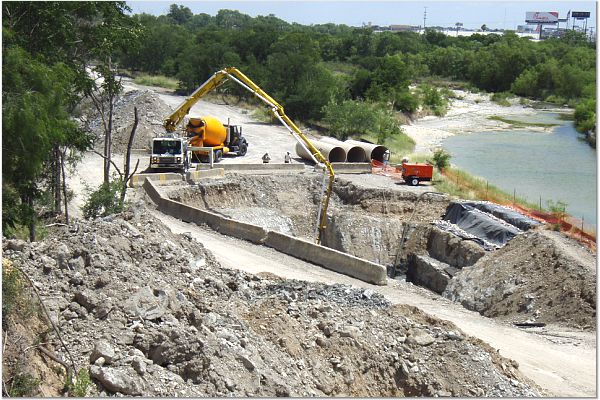
A good example is the nearly completed Western Watershed Sewer Relief Line W 04 project, said Andrea Beymer, P.E., SAWS project engineer. The $19.8 million project included the construction of approximately 11,250 linear feet of 66 inch and 60 inch diameter sanitary sewer mains to replace the existing 42 inch main in a highly urbanized area of San Antonio. The old pipe was abandoned.
Engineering for the W 04 segment was done by Weston Solutions Inc., San Antonio. General contractor was BRH Garver Construction, Houston.
As designed by Weston, the improvements of the project would include 1,832 linear feet of 60 inch and 9,422 linear feet of 66 inch FRPM (fiberglass reinforced plastic mortar) pipe, with the depth of the interceptor ranging from 10 to 55 feet below ground surface. The project also encompassed the design of six lateral connections to the rerouted collection system including 1,341 linear feet of 8 inch; 659 linear feet of 15 and 18 inch; 459 linear feet of 24 and 36 inch; and 34 linear feet of 48 and 54 inch pipes.
Open cut construction was used wherever possible, but because surface improvements limited access in many areas, depth requirements for the new pipe, rocky subsurface conditions in many areas, nearly half the construction was completed by tunneling.
“Alternatives analysis included evaluation of pipe materials, construction methods and routing,” said Abdel Hamed, P.E., Weston Solutions. “Probable costs of each alternative were developed and compared including a net present value analysis. Non monetary considerations included utility locations, constructability, traffic concerns, environmental/permitting issues, community impacts, right of way/easements, operation and maintenance concerns and manhole junction structures.
“By dividing the 11,254 feet of sewer into 14 reaches’ and specifying the acceptable construction methods for each reach, design documents allowed bidders flexibility to choose alternative construction methods.”
Water, water and more water
The project’s location in an area subject to serious flooding posed challenges from the beginning and delayed the start of construction.
The critical path at the beginning of any construction project is surveying and construction layout, said Dan Deemer, project manager for contractor BRH Garver Construction.
“This is especially critical when working in a flood zone such as Leon Creek,” he continued. “Survey markers are no match for flood waters. They wash away or become covered by sediment and are unrecoverable. This was a major issue for us during our attempts to start the project. During the months prior to and after our Notice To Proceed in July 2007, San Antonio received record breaking rainfall amounts which caused dangerous flooding conditions along Leon Creek.”
The ground was already saturated from the prior floods and to make matters worse, San Antonio received five times the average amount of rainfall for July 2007, the month construction was scheduled to begin.
“Leon Creek remained at dangerously high flood levels throughout July and August of 2007,” said Deemer. “San Antonio received double the average amount of rainfall in August 2007 due to remnants of Tropical Storm Erin, preventing any chance of the flood waters receding. Survey stakes placed between flood events were washed away.”
The last flooding came in September, causing 64 days to be lost on the project before work even started.
“We had to commit this shaft crew to a different project temporarily and then brought them to San Antonio at the first opportunity after the floods receded,” said Deemer. “This had a ripple effect on the tunnel machine delivery to the site. We did not want to bring the tunnel machine out before the tunnel shaft was ready. The moment it was ready, we proceeded to mobilize the tunnel machine and place it in the shaft.”
Tunneling
Juergen Brunswick, lead tunneling foreman for the project, had these comments about the tunneling operation:
“We knew that we were going to be encountering rock with a psi range from 3,500 psi to almost 5,000 psi. We prepared our Lovat M90 tunnel boring machine (TBM) by replacing the 150 horsepower motor with 200 horsepower. This gave us some additional pump capacity for the machine. We also changed our air cooled system to a liquid cooled system. In addition to the added power, an additional benefit was a cooler tunnel for personnel to work in.
“Based on the geotechnical investigation we installed bullet teeth on the cutter and made the first run. We experienced mixed ground conditions that made us rethink the cutter setup and we changed to a combination of bullet teeth and rippers for the rest of the project. This allowed for greater steering control and better production rates in these mixed face conditions.”
Pipeline depth of tunnel sections varied from 25 to 45 feet. Carrier pipe was Hobas fiberglass reinforced pipe with 46 psi stiffness. Annular space was grouted with low strength cellular concrete.
Brunswick said ground water was not an issue even though the tunnel was immediately adjacent to the creek.
“We had a closed face setup on the TBM and we installed filter fabric material around the lagging [ring beams] of the tunnel itself,”he explained. “This allowed the ground water to infiltrate the tunnel and run out to the tunnel shaft while filtering the solids. We tunneled uphill to keep the water behind us at all times.”
In addition to using the Lovat TBM to tunnel, Deemer said a subcontractor assisted with hand mined tunnels. The primary liner was 96 steel liner plate supplied by American Commercial. The steel liner plate was an acceptable material to use as a primary liner on each of the three road crossings including two Texas Department of Transportation easement crossings.
“This additional manpower assisted in narrowing the lost contract time due to the floods,” said Deemer. “The basic tools were a jackhammer, clay spade and a muck bucket. We put the muck bucket on tracks and wheeled it in and out of the hand mined tunnel to the come out pit where it was lifted out of the pit with a crane and emptied. We kept muck buckets in rotation so we never lost time due to dumping.
The average open cut depth for this project was roughly 30 feet.
A Caterpillar 350 excavator equipped with a breaker was used to assist a Komatsu PC1000 excavator for digging the trenches.
“In areas where the breaker was not efficient enough, we hired a subcontractor to use a four foot wide rock saw to cut the hardest rock down to grade on both edges of the trench,” Deemer said. “We then chipped out the remaining rock in the center of the trench with the PC1000. Ground water encountered during the open cut process was addressed with numerous pumps in the pit to keep the work area dry.”
Funding
The wastewater component of the capital improvement program focuses on sustaining aging collection systems, maintaining compliance with regulatory requirements and supporting wet weather and operational demands, said SAWS’ Beymer. A major focus continues to be repairing and adjusting wastewater mains in coordination with the City of San Antonio’s bond program.
Collection system projects funded in 2009 will rehabilitate critical mains and also continue to add capacity in the rapidly growing far west area of the city. It also funds the continuation of a comprehensive lift station assessment and rehabilitation program that will ensure these critical facilities remain in full compliance with state regulations, industry codes and best management practices. Large collection lines in the central and western watersheds will be upgraded to expand their capacity.
The wastewater treatment component of the 2009 capital improvement program includes projects that will replace or upgrade aging components and processes and address safety concerns at the Dos Rios treatment plant.
FOR MORE INFORMATION:
Contractor: BRH Garver Construction L.P., (713) 921-2929, www.brhgarver.com
Trenching contractor: H.L. Chapman, (512) 259-7662, www.hlchapman.com
Pipe: Hobas Pipe USA, (800) 856-7473 or (281) 821-2200, www.hobaspipe.com
Excavator: Caterpillar, (309) 675-1000, www.cat.com
Consulting engineer: Weston Solutions, (210) 308-4300, www.westonsolutions.com

Comments